Objectives:
- Control an output device with a microcontroller
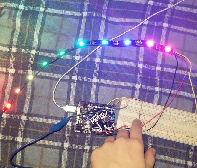
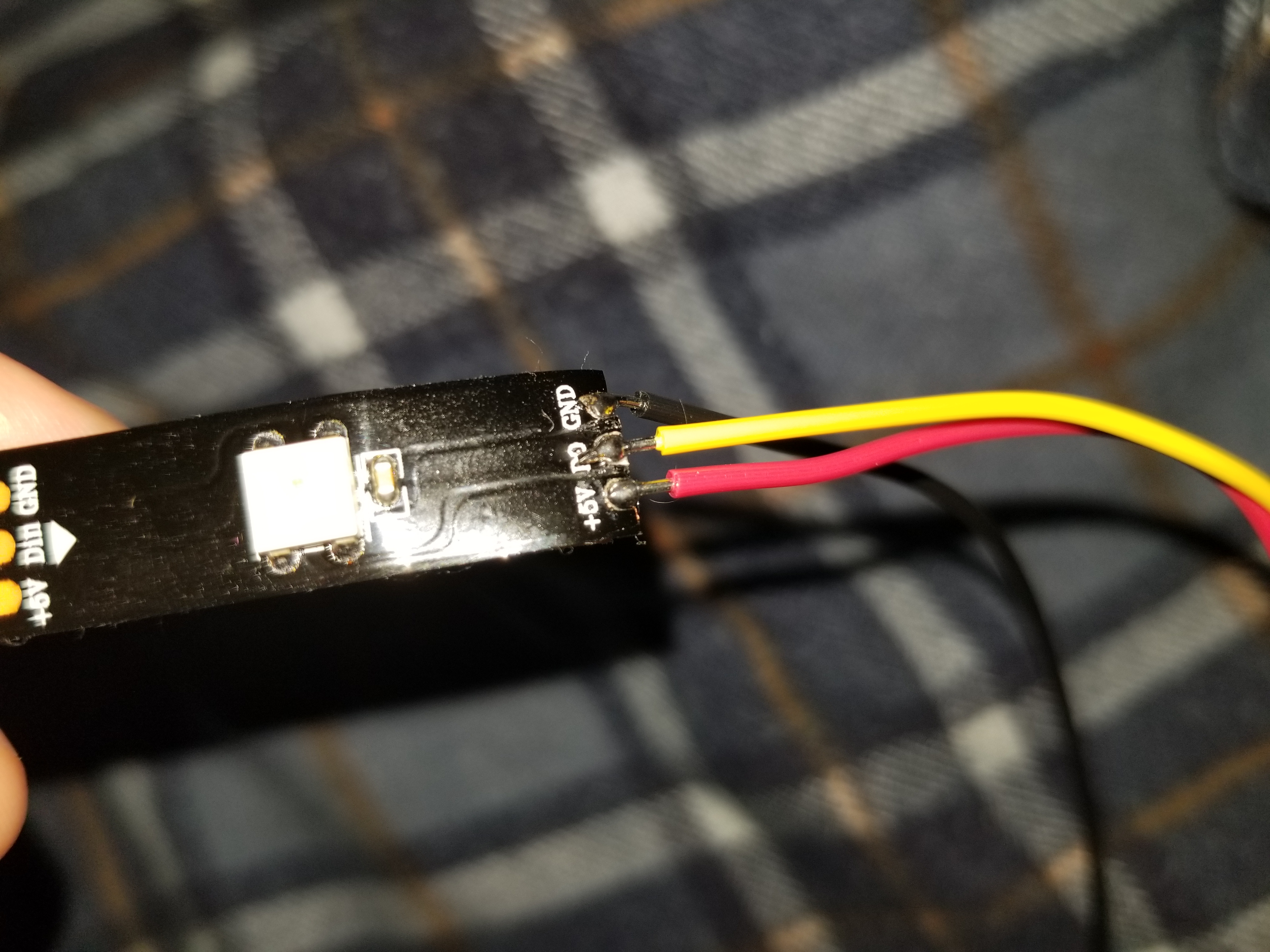
For this week, I wanted to learn more a about LED strips since I'd never used them before. My goal was to make the sample code from the Neopixels library work. In failing at making the strandtest code work, I realized that I couldn't use the wire soldered on DO, because I needed the Arduino connected to DIN (Data in) to change the state of the lights. I did this by attaching an alligator clip to DIN and connecting that to a wire from the arduino channel. The fact that GRN and 5V were soldered on the opposite end of the strip didn't matter since Neopixels can be powered and grounded from either end.

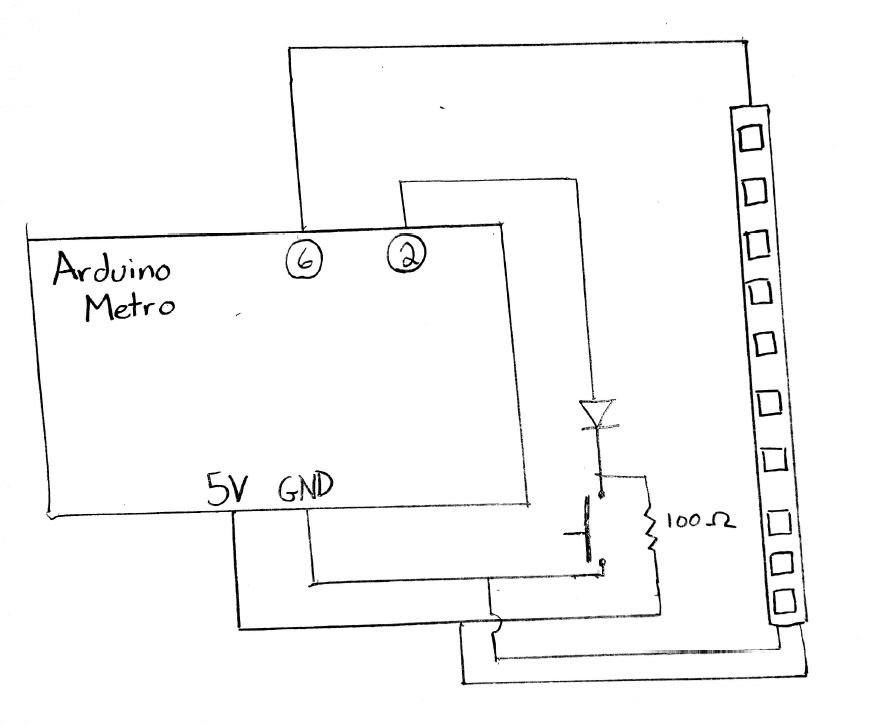
Here is the schematic which shows how the circuit was constructed. The box represents the Arduino Metro and the circled numbers inside represent different pins. This circuit features a pull-up resistor which causes a High to Low transition for pin 2 when the button is pressed. There is also a diode to reduce noise. The LED strip is attached to just ground, power, and pin 6.
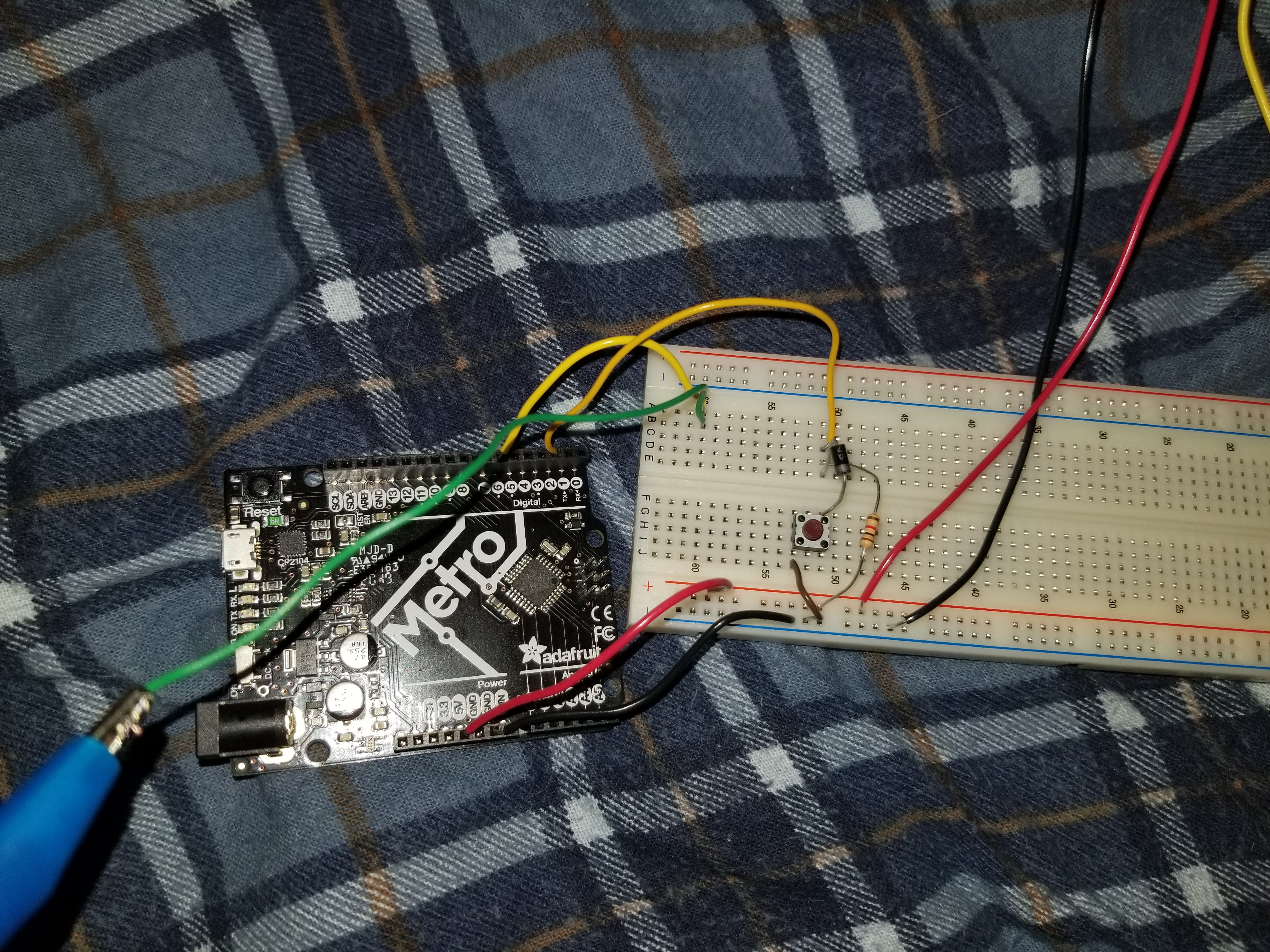
Here is what my circuit looks like when built:
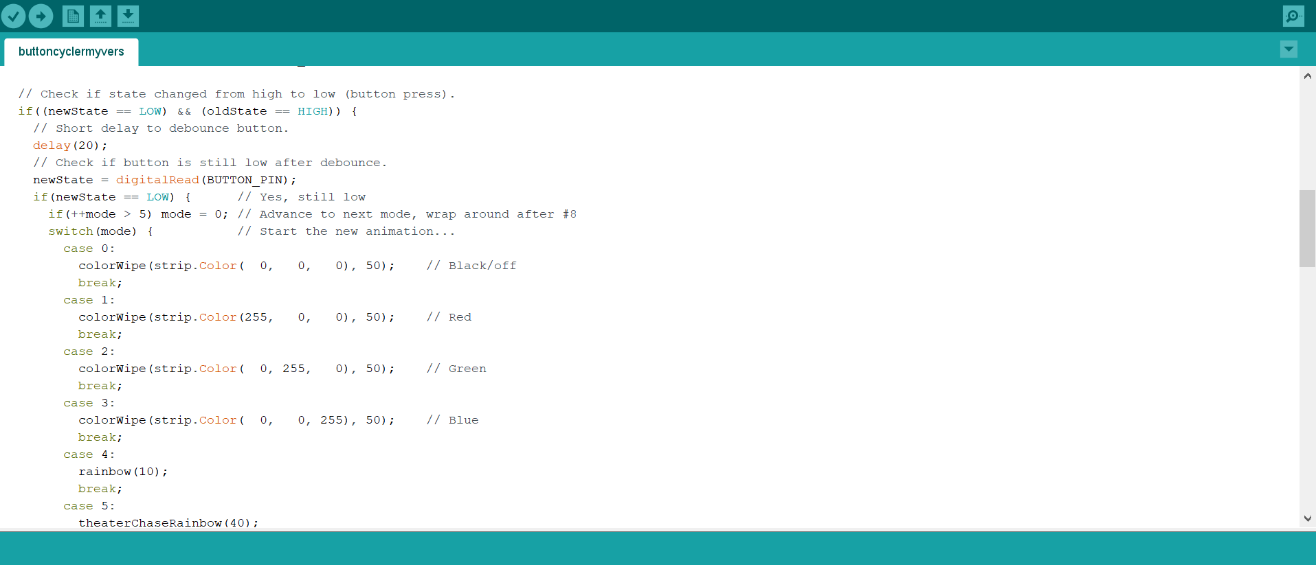
As for the code, I used the buttoncycler example code found in the Arduino Neopixels library. I made some modifications, making the modes the ones I liked the most. I also played around with the speed each mode runs at. Here is a screenshot of the code that was changed:
Here is a video showing the LED strip changing through 5 modes with a button press.