Objectives:
- Understand the basics of electronics
- Learn how a breadboard works
- Construct a basic circuit that lights an LED
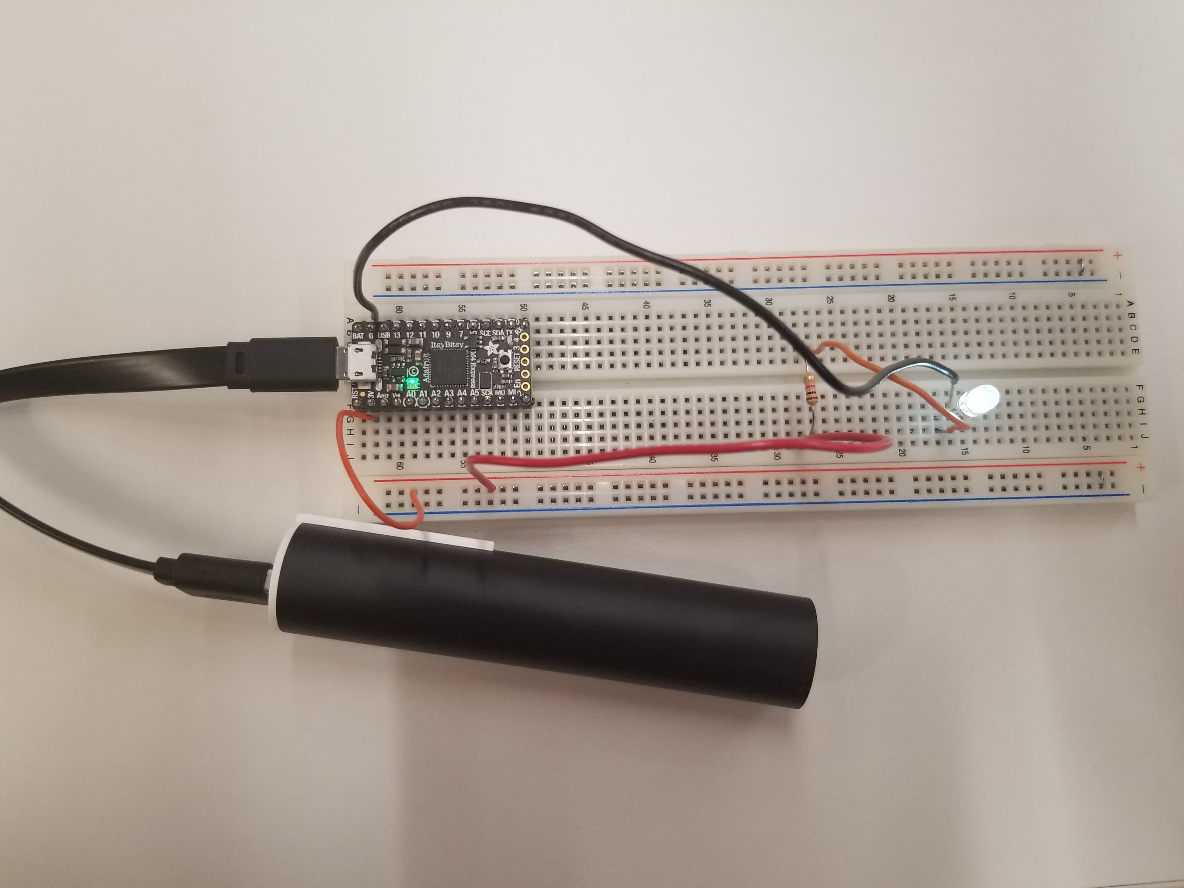
Circuits work by utilizing a difference in electric potential. By creating a path for a region concentrated in electrons to conncect with a region of low concentration, a circuit can direct the movement of electrons, driving them throw devices to power them. In the simple circuit pictured above, electrons are powering the LED light.
Underneath the plastic cover, a breadboard is composed of thin metal strips which direct current in a specific way.
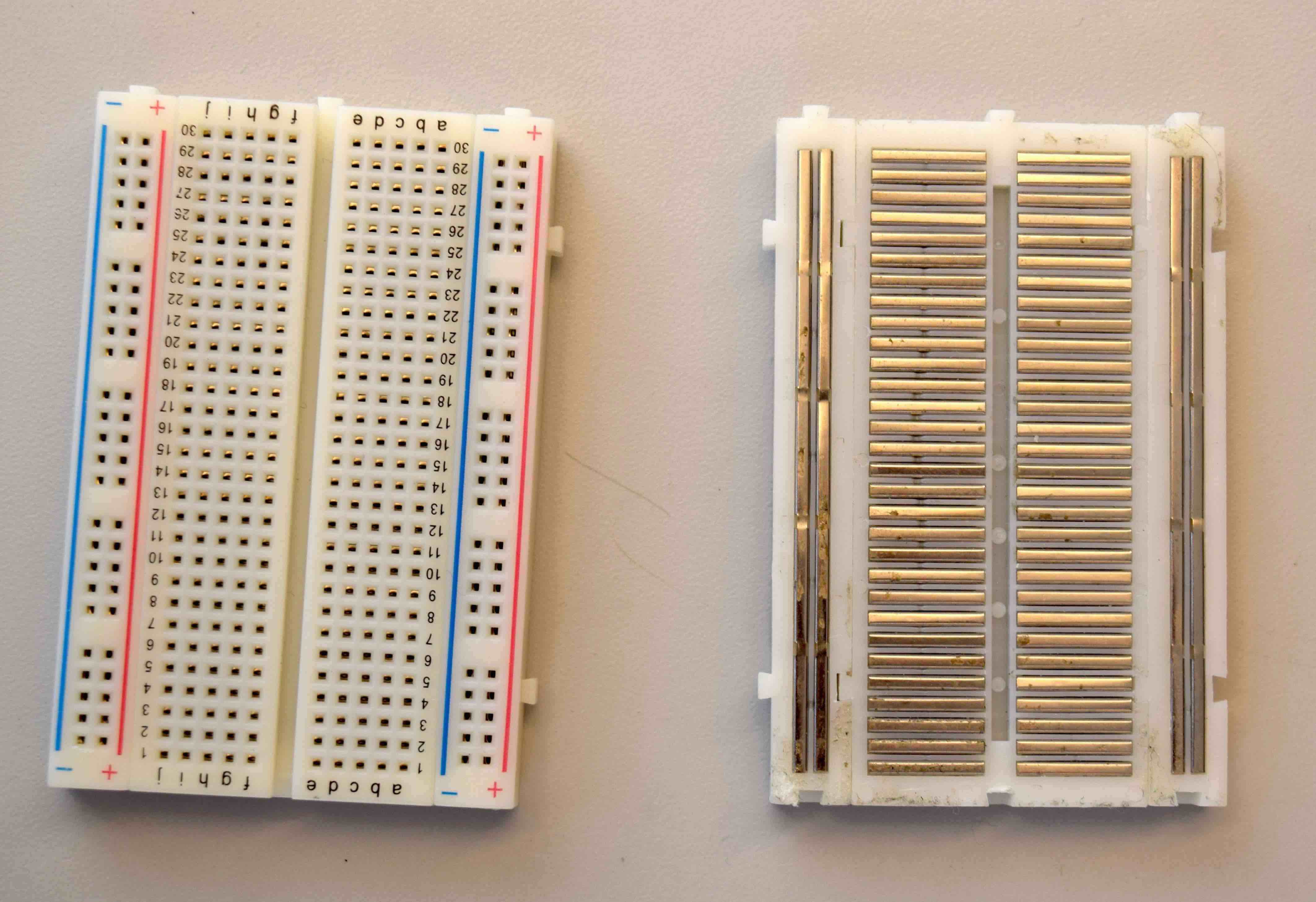
In order to create a complete circuit in which electrons can flow from start to end and power our devices, we need to connect our wires to the board in the orientation of these metal strips so that current can flow in the whole circuit.
We will be using the Adafruit ItsyBitsy M4 microcontroller to power our circuit. To attach the microcontroller to the board, simple press all the pins of the controller into the board until the board and controller meet. The micocontroller should not sit loosely. To start our circuit, we will connect a wire into the slot next to where the microcontroller says '3V'. This tells us the number of volts going into this circuit will be 3. A higher voltage is unnecessary as it will burn out our LED.

Although there is a lot of freedom for how we construct this circuit, we must make sure that it ends where the microcontroller says 'G', which stands for ground. This is crucial for getting current flowing through the circuit to make it work.
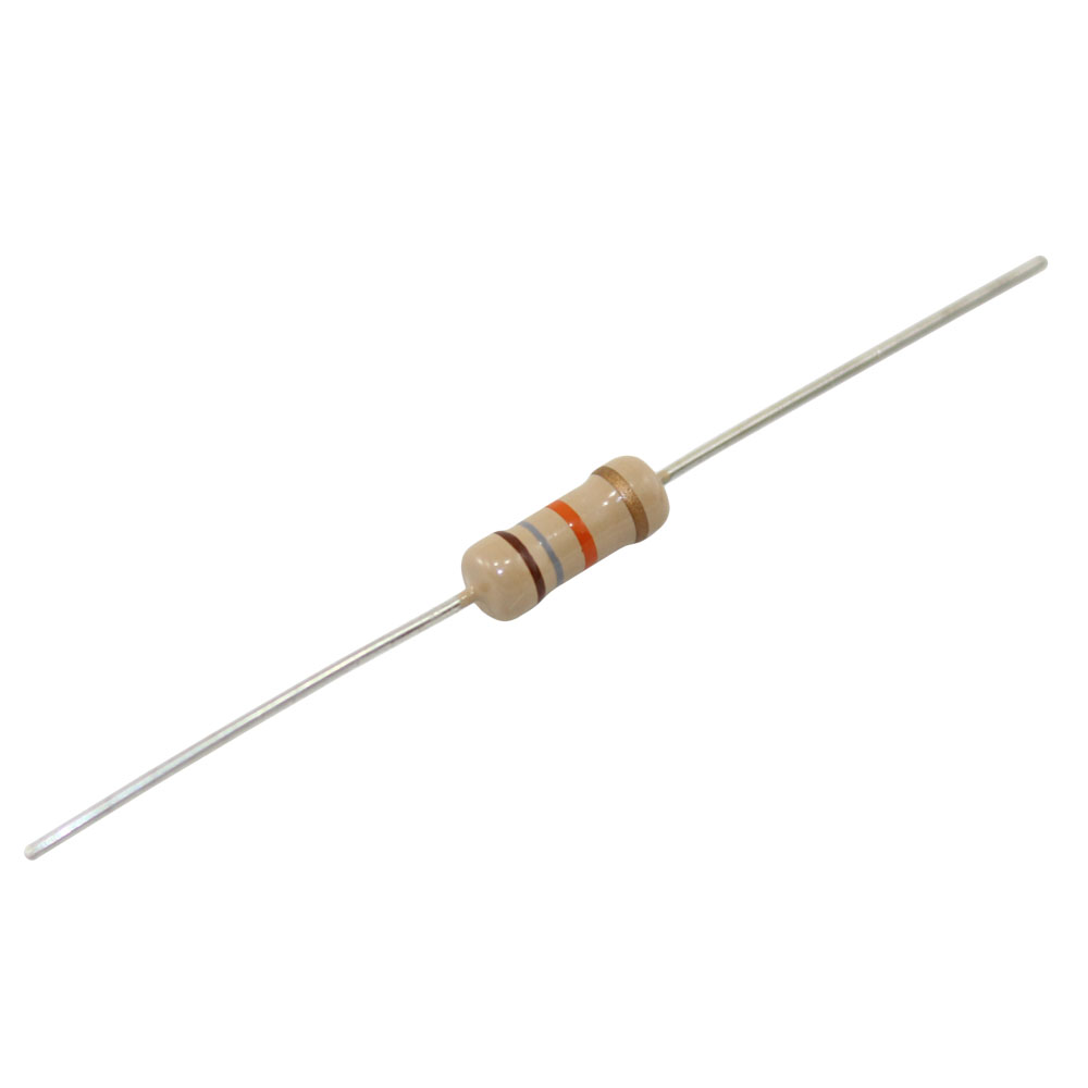
Another important step to note is that we need to place a resistor (pictured below) before our LED. This limits the current flowing into the LED to prevent it from burning out. By limiting current, a resistor also creates a drop in voltage. For the LED, the longer leg is the positive end which must be placed first in the circuit. The shorter leg, the negative end, needs to lead to ground. The positive and negative terminology is just a convention for describing how electrons need to flow through circuits and devices (positive meaning in and negative meaning out).

Now all that's left is to connect all these pieces with wires following the orientation of the breadboard and... voila! You have created your first circuit! Plugging a battery pack into your microcontroller should reveal to you a brilliantly glowing LED, brighter than any dream in the universe! If not, you may need to recheck your wiring.
Using a multimeter (pictured below) we can connect the red wire (positive, facing 3V end) and black wire (negative, facing ground) at different points in the circuit to get a reading on the voltage between those two points.
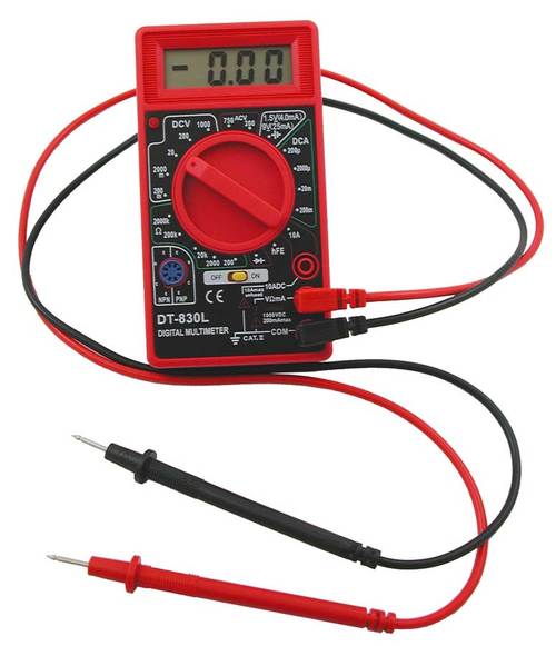
When both rods are placed before the resistor, we should get a reading of zero since there is no change in the voltage. When the red rod is placed near 3V and the other is placed just after the resistor, we should get a reading of roughly 2.6 volts since the resistor limits the current and thus the voltage. When the black rod is placed after the LED we should get a reading of roughly 3 volts since the resistor and LED are using up so much current that the change in voltage here is the largest.