Objectives:
- Learn the basics of Autodesk Fusion 360 and make a simple model
- Learn how to use a laser cutter
- Create a cardboard construction set
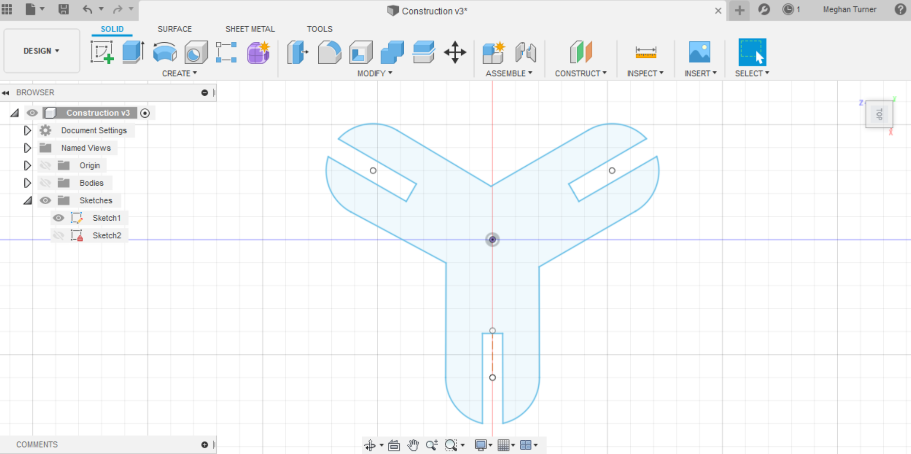
For my construction set, I wanted to create circular structures from non circular parts. For this goal I envisioned a three pronged piece with prongs 120 degrees apart from each other. Fusion had a bit of a learning curve to it but after establishing some construction lines to act as guides for the rest of the, I was able to create a single prong in a 2D sketch. Now that I had a single prong, I could use the circular symmetry function of Fusion to make the other two pieces exactly where I wanted them to be.
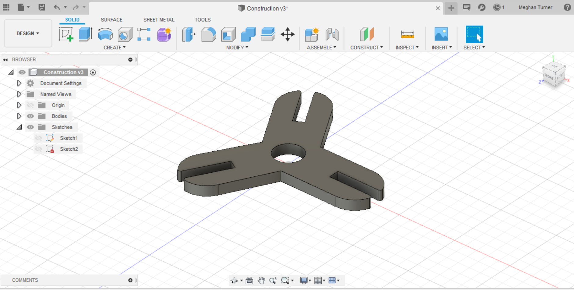
After I made my 2D sketch, I was able to extrude it into a 3D model. Using set parameters, I am able to change the thickness of the slots so I can change the entire model by changing one value. I decided to fillet the sharp corners of the slots so they wouldn't become damaged from assembling the pieces. I also added a hole in the center to make it more stylish. I now had a 3D model that looked like this:
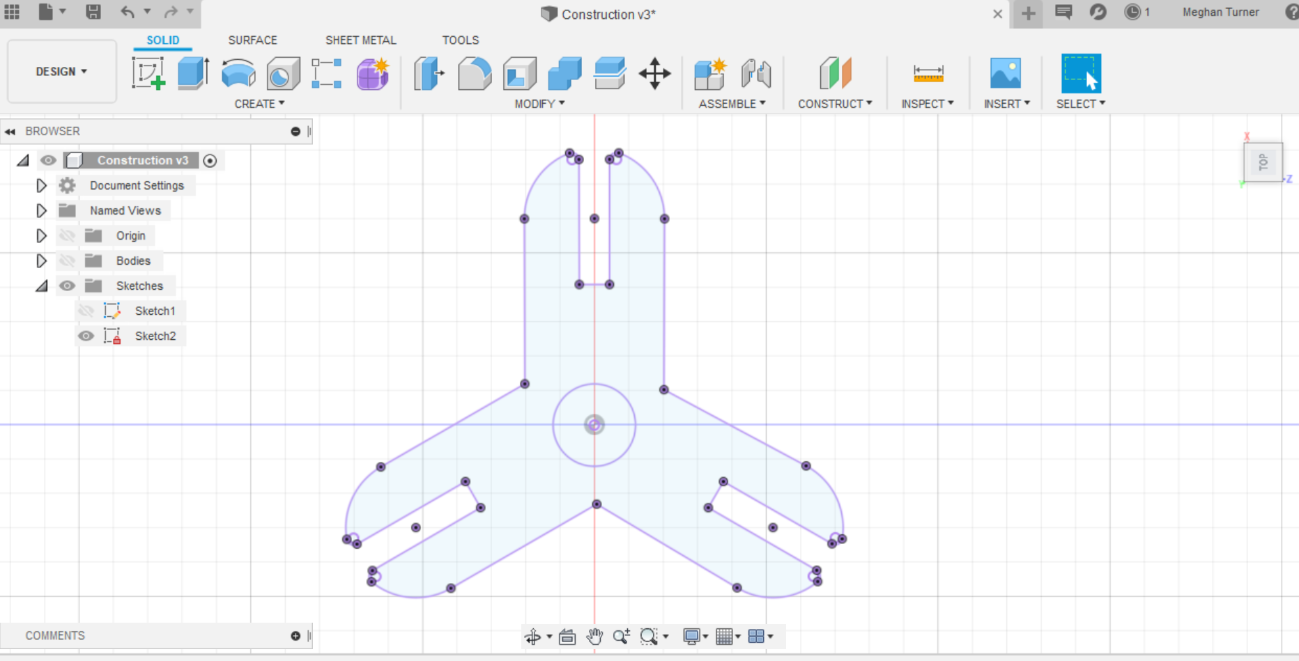
Before cutting the piece, I had to get the model into a form the laser cutter could recognize. To do this, I had to make a projection of the 3D model so it could become a sketch again, containing all the points necessary so the laser cutter knows how to trace the figure.
Using the laser cutter to print the piece was actually far simpler than I anticipated. I uploaded the projection onto the laser cutter via a flash drive. With some help from Nathan, I set the laser to the right specifications for cutting the cardboard. From there I manually moved the laser to a spot on the cardboard that had not yet been cut and hit the 'origin' button to give the laser cutter its starting point. Pressing 'trace' on the computer allowed me to see if the cut was too big for the area I had chosen. I then closed the hood and clicked 'start' on the computer to beginning cutting my first piece.
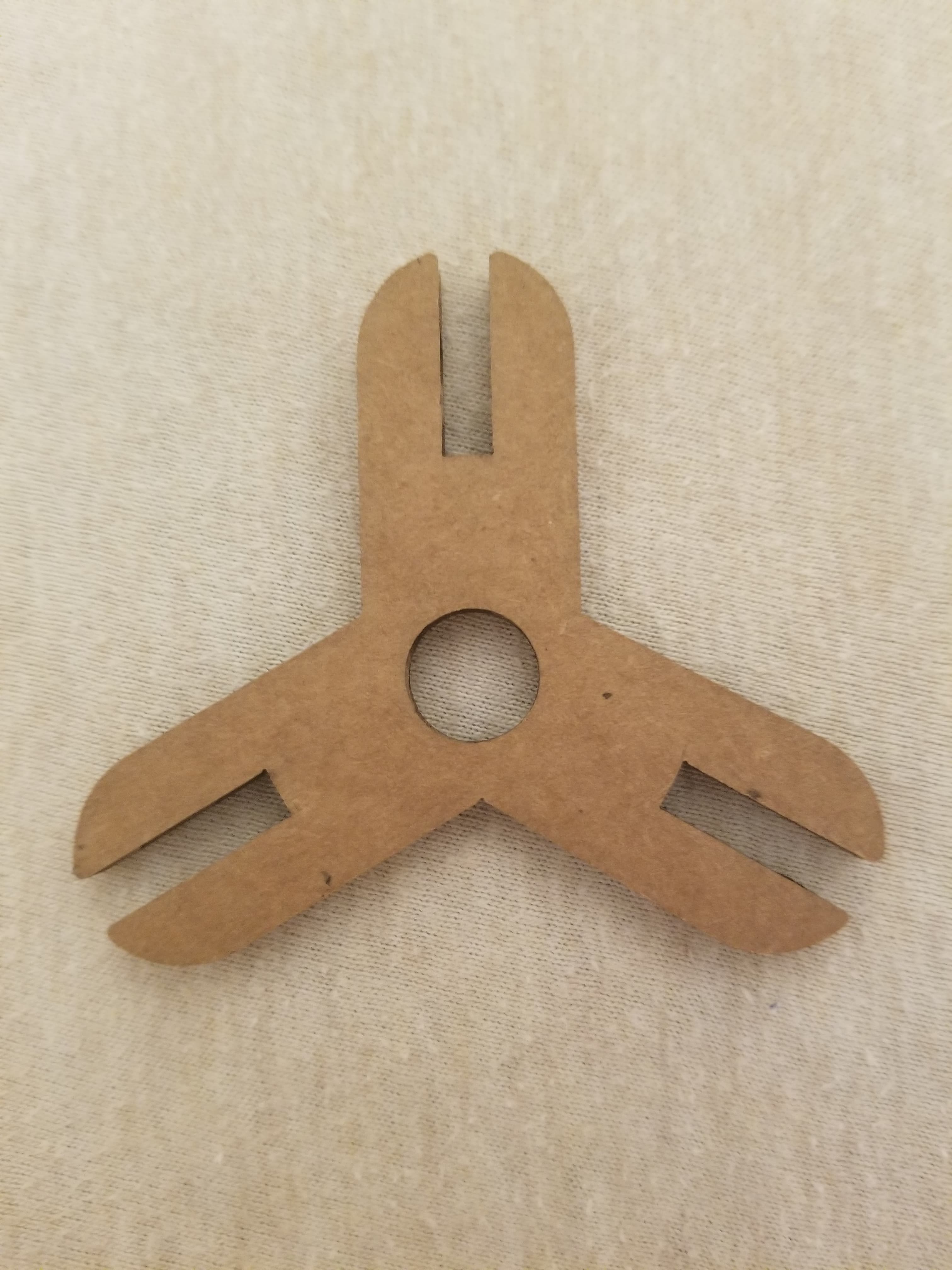
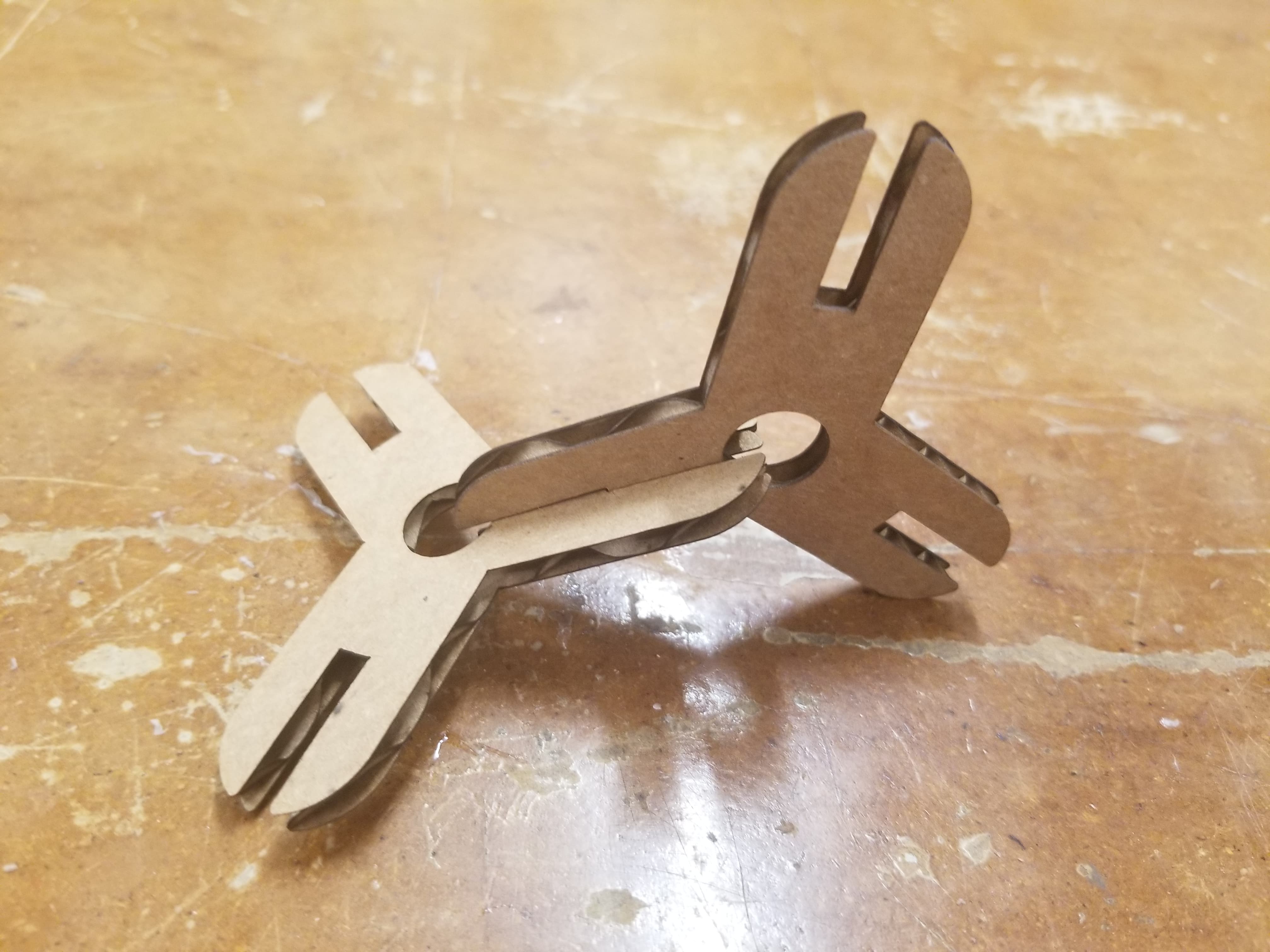
And here is my finished piece! After laser cutting another one, I was able to test if they behaved the way I wanted them to.
In designing the digital model, since it was my first time ever creating one, I ended up just guessing on most values without actually knowing how practical they were. From having cut the shape I can see that I need to go back and decrease the thickness of the slots so they have a tight enough hold that the pieces won't fall apart when assembled. Additionally, I need to decrease how far into the piece the slots go. Because the slots were so long, connecting the pieces resulted in an overlap into the hole at the center of the piece. I'd also wanted to increase the fillet to greater than 1mm to protect the piece from damage over time. After these corrections, I'd like to cut more pieces so I can get a sense of the structure they make.
Additionally, I also have some plans for more abstract construction piece designs such as using the golden angle to create pieces that when assembled, make strange repetitive patterns. I'm not sure if I want to make a two pronged piece or a circular piece for more slots to let the builder choose between 135.7 degrees and 222.5 degrees. Hopefully I'll be able to make both so I can explore how mathematical ideas apply to real life structure and functionality. If there is any progress in this endeavor, I'll record it under a 'updates' header on the bottom of this page.