Objectives:
- Make a capactive sensor
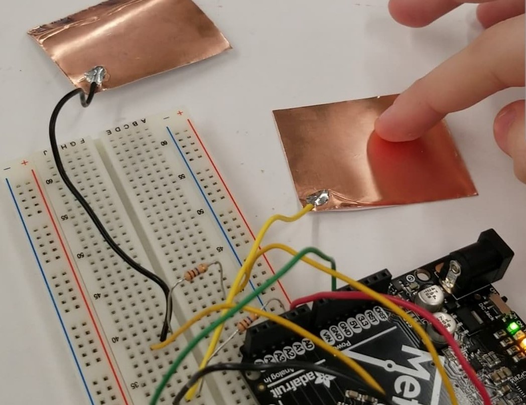
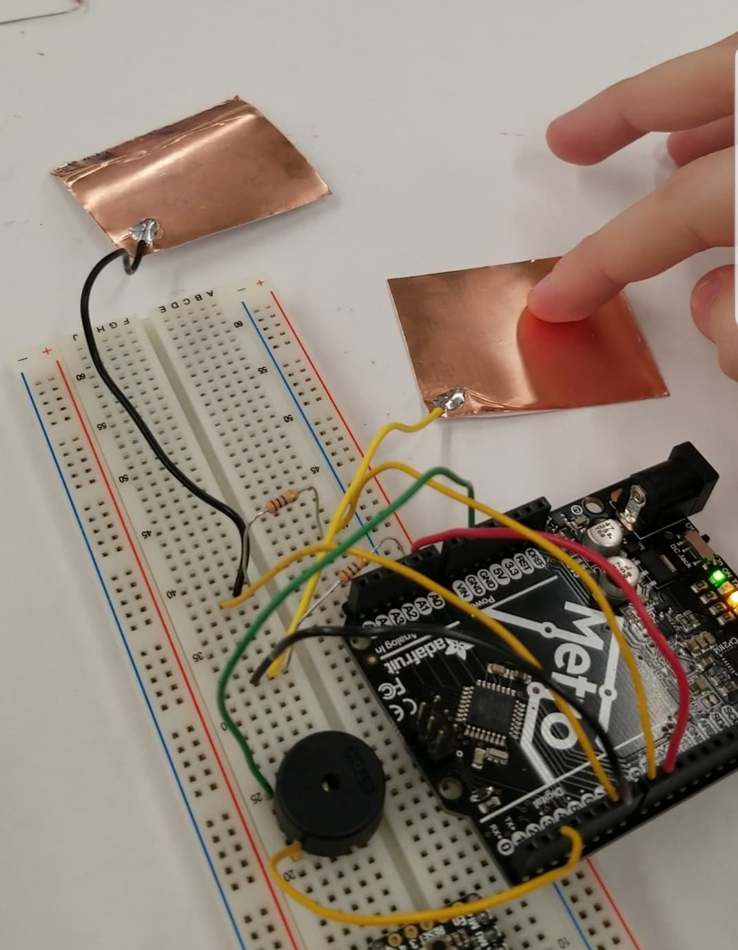
For my project, I wanted to make a simple keyboard and explore the tone function in arduino in preparation for my final project idea. I've set up a circuit that uses two capacitive touch sensors to produce three distinct tones when touched. Each one touched separately produces a distinct sound and when both are touched, they produce a new sound. Each capacitive touch sensor exists in its own loop and its output decides the input for the buzzer in the circuit.
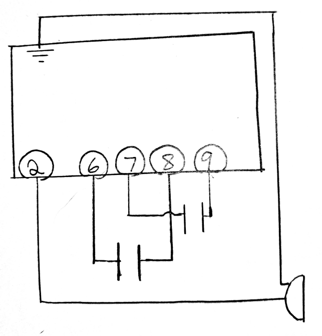
Here is the schematic which shows how the circuit was constructed. The box represents the Arduino Metro and the circled numbers inside represent different pins.
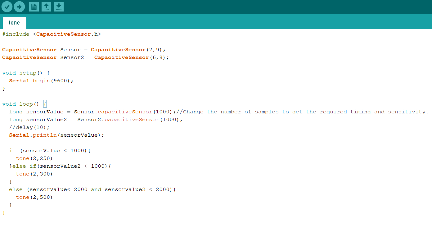
In the code I define each piece of copper tape as its own capactive touch sensor using commands from the capacitivetouch library. 1000 is an abritrary value I chose from guessing and testing. I had to raise the value in the condition where both sensors are pressed because I was decreasing the resistance by linking the sensors with my hand.
Here I've filmed myself demonstrating the circuit's three tone capability with only two sensors.
The fact that the circuit produces the tones I specified tells me that the code works fine. However, the circuit is a little unpredictable. I found it making sounds when nothing was pressed or changing rapidly between two tones when one was pressed. This could be because of how close I had the sensors to each other and to the arduino board. In making my final project, I want to make a clear separation between the components so I know nothing else is affecting the resistance of the touch capacitors.